Sunday, September 27, 2020

Re-Assembling the Steering Column

Little did I know what awaited me as I reassembled the column (I was thinking because I had dropped a shift collar flange screw (yes - Ford part #3461 the square headed one) down into the column between the auto shift sleeve and the outer sleeve -- I would have to remove the complete column assembly to retrieve it). I found that by taping a rare earth magnet (o'reilly's $4) to a straightened wire hanger I could slip the magnet down between the column shaft sleeves and pulled out my flange bolt. My first block was eliminated. 

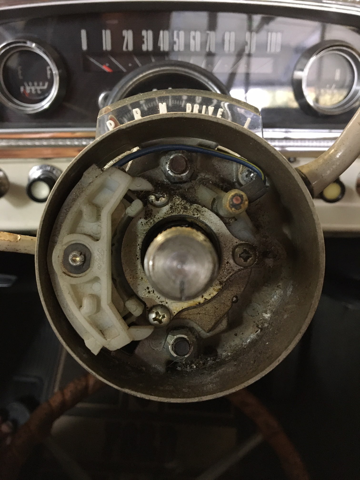
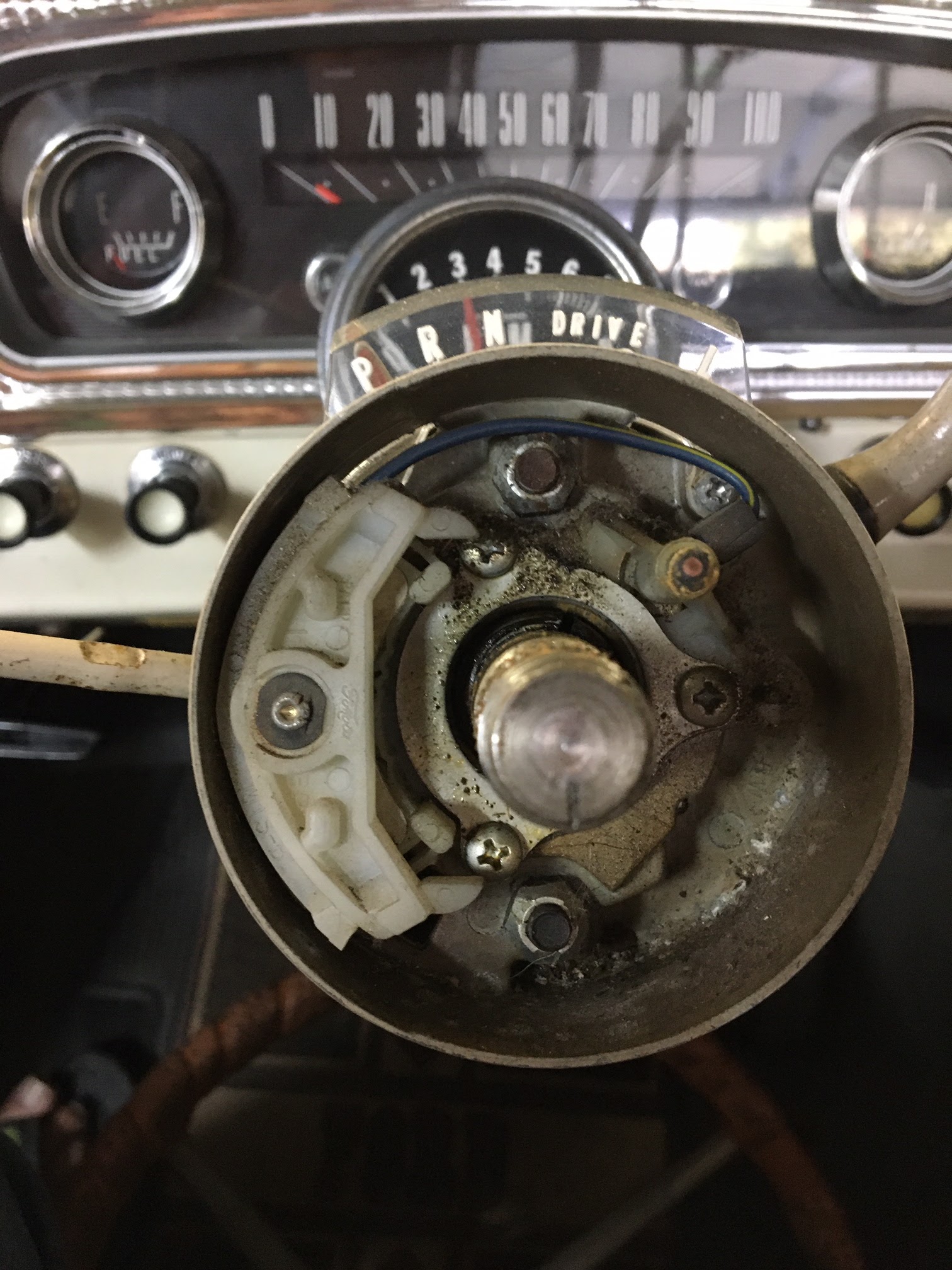
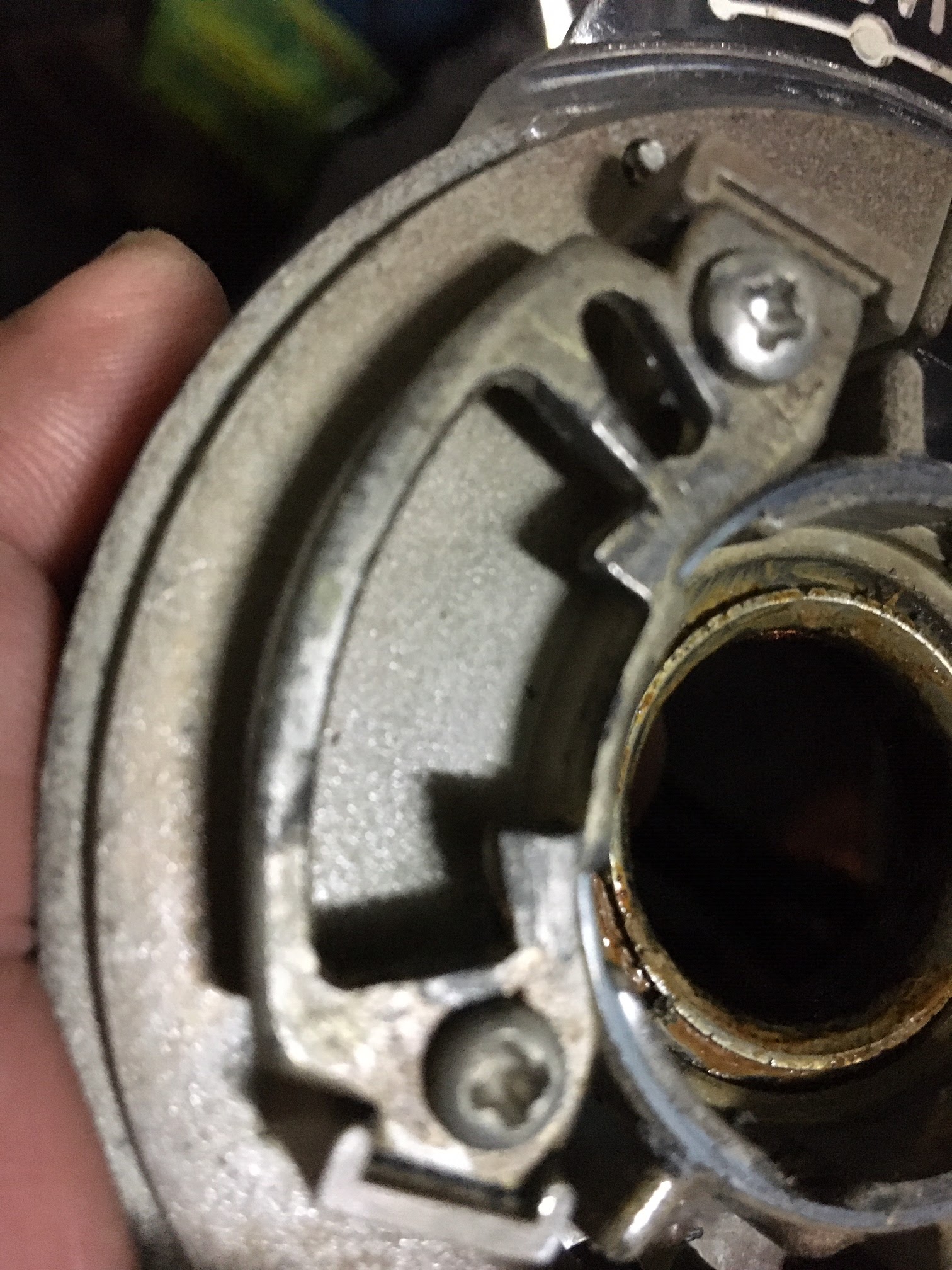
\Next, after dealing with all the wiring and placement of the new turn signal switch into the signal flange collar I was stumped by how the flange bolts actually worked - what did they do? They seemed to just sit in the signal flange and after tightening when I tried to marry the signal flange to the shift collar there was about a 1/8" gap between the two and no way to connect them. Spent a few minutes looking at pictures I took during the tear down and at the various sleeves in the column before I realized the heads of the flange bolts need to sit in top and lower slots of the outer column sleeve. 

Slots on Top & Bottom of column

Now, how to get them mounted. I spent a few days searching before I found someone that had the same question with a '65 falcon and they had two recommendations - mount flange bolt loosely into signal flange and wiggle signal flange onto column sleeve until flange bolt heads find slots then tighten - OR - tape bolts into slots and then slip signal flange onto bolts and tighten.

I loosely set the bolts and nuts in the signal flange, slipped it over the column and jiggled until the heads of the bolts slipped into the slots on the column - was NOT difficult! However, then the next challenge as I tightened everything down and slipped the steering wheel into place - no matter how much I tightened the main nut on the wheel, the wheel and steering rod were very loose, not like they had been before. 

I spent the next 2 days taking apart and rebuilding the steering column, shift collar, signal collar and searching everywhere on the web for hints at what was wrong - most mustang, falcon and truck owners over the past few decades all pointed to a missing spring between the top bearing sleeve and the steering wheel as the culprit - but I didn't have a spring except for the horn spring in the pieces I had removed - I even went back through all the pictures I had taken but did not see the spring everyone was saying should fix my problem. 

Seems I am missing Ford Part Number 3520 from the parts catalog blow out view of the steering column. Hmmm ... 

I looked around but couldn't find a spring anywhere until I climbed over the tools and packages sitting on the bench seat and looked down on the floor by the passenger door - there, laying against door was my spring - it had rolled off the seat sometime over the last 4 days and now I slipped it over the steering rod and mounted the steering wheel - WOW! Wheel was smooth, tight, my turn signals worked left and right, and most important for me, PARK actually stayed in PARK. 


All the pieces are required ))

I connected the battery and .... the horn starting blasting ))) Uh ohh, something wasn't right, I took another look at the plugs and wiring coming from the steering column but nothing looked incorrect. I connected and re-connected all 7 wires from the connectors and reseated each, verifying the cables were in the correct position, when I touched the cable to the battery the horn blared. 

I compared starting pictures with what I had built, I reviewed threads on FTE about rewiring the column - there was no easy answer here so ... I pulled the horn ring ... and then the steering wheel ... I connected the battery and it beeped - I knew something was shorted somewhere, so I disconnected the turn signal switch ... still beeping ... pulled the turn signal switch up off the steering rod ... touched the battery cable to the battery and ... silence ... hmmmm, I remembered what a teacher had told me years ago - the last thing changed before it broke is what broke it - so I took a close look at the wires on the back side of the turn signal switch, compared what I saw to the broken, original switch and saw that the horn wire wasn't mounted on the new third party the same way that the OEM part had. I unbent the wire where it was connected to the switch and made sure the wire routed up over the switch and down the column. I touched the battry cable tot he post and ... no beeps!     

I quickly reassembled the steering wheel and horn ring, cabled the battery and ... no beeps until I pressed the horn ring - it was working. I fired up the truck and tested the left and right turn signals ... worked great. 

After 8 years of running this old truck without PARK (blocking wheels whenever I parked, using parking brake religiously, etc.) I feel a little spoiled knowing that when I slipped Ole Blue into Park she ain't gonna move until I am sitting in the drivers seat again. 


Tuesday, September 22, 2020

How to Drive a Ford Cruise-O-Matic Transmission in Town


The Cruise-O-Matic arrived in 1958 and offered 3 Drive positions, one marked with a green dot. The new automatic still featured a Low position, but a sprag allowed the transmission to shift automatically from low to second to third when in the green dot position. The white dot started in 2 gear and went to 3rd only. This green dot gear pattern remained until 1967, when Ford replaced it with the now-common 1-2-D pattern for three-speeds. 


Frankly, weekend runs down the boulevard using white dot is comfy, responsive (with the 352) and there ain't a day goes by somebody doesn't give me the thumbs up ))


From the original 1966 F-250 Camper Special Operators Manual we learn what the crazy dots and L mean when driving the 3 speed Cruise-O-Matic transmission. 

I think the cruise-o-matic (or COM) is a little quirky and a little special - I know nothing of the mechanics but from a drivers view, skipping first gear on a truck geared like this factory standard Spicer/Dana 60 Rear Axle (4.10-1 / No Limited Slip with 5,200 lbs. Rear Axle) made off farm driving a piece of cake. I don't get ice or snow but I find the 2-3 softens the jolts when driving in town and out on the two lane roads in the surrounding low hills. Downside is there is no way to hold the transmission in 2nd gear. On all forward options 2nd gear shifts up.      


I never could resolve the differences in the drive markings of the picture on page 1 and the text. So, I drove it to learn the green dot on my shift indicator shifts 1-2-3, the little white dot under the word Drive started in 2nd and went to 3rd when pushed. L was 1st gear only.   


Best of luck with this ... 

Monday, September 21, 2020

Replace the Automatic Transmission Shift Lever

Because the shift lever tab that holds the lever in Park was snapped off over the years (even resulting in replacing the drivers side door when Ole Blue took off across the yard while tuning and side swiping another parked car) we found an New-Old Stock (NOS) OEM shift lever on Ebay and want to swap in the new shift lever.

Ebay is our friend today - WooHoo (nice Price!!!) 


Its a black one, not tan but will work with Ole Blues Interior 


Install

First - we looked around and found the following guidance:

"... Use a punch and hammer to drive the pin from the bottom up. Probably easiest if you select reverse or second gear. Once you drive the pin out, you'll be holding the lever in your hand. " https://www.ford-trucks.com/forums/915143-1966-ford-gear-shift-lever-removal-question.html

OK this seems straight forward... but it took 3 days of very careful placement of the punch (I did not want to mess up the original paint on the shift collar) to figure out how hard I had to hit the pin to push it up. You have to smack it fairly crisply and solidly to get it to move, with shift collar firmly placed on stack of newspapers of something else that will keep paint from chipping off of pressure points. 

Once the pin was out the new shift lever slipped into the shift collar with a little wrangling with the spring loaded pin that MUST be under the shift lever. By turning the shift lever just enough and sliding it into the shift collar while pressing it against the engine side pressur epin the shift lever slipped into place. I inserted the pin from the top down into the collar and lever and viola! New lever for ole blue! 


Wednesday, September 16, 2020

Yuuup - its the old Park to Reverse issue common on F250's with a Cruise O Matic

When Ole Blue is sitting in Park, it frequently will slip into reverse. Happens when starting, when sitting at a stop light, when idling in the garage during a tune up. When Uncle Ken was having Ole Blue worked on in the 90's the mechanic wasn't aware of the issue and actually tore off the driver side door when he left the door open while working up front and the transmission slipped into reverse, idled across the yard (in reverse) and hit a tree or something bending the drivers door towards the front of the truck -- AAACCCKKK. (They found a replacement door and painted it to match Ole Blue's Marlin/Wimbledon colors - it still doesn't fit very well - maybe was off a '64 or something).

Anyway, I was reading threads on the FTE forum the other day and saw where Bill the retired Ford Parts Manager responded to a reader with the following info:

"What you're referring to...is not a defect, it's caused by human error. It's a somewhat common occurrence that affects all 1961/96 trucks with A/T.

People put the shift lever into Park before setting the hand brake, causing the truck to roll...just enough...that the parking pawl inside the trans locks up tight.

Now the shift lever has to be YANKED out of Park and before too long, the detent aka shift gate that the tab on the shift lever locks into between Park & Reverse...snaps off.

C5TZ-7A216-A ... Detent-bolts to bottom of upper steering column flange ~ 1965/66 F100/250 240/300 C4 & 352 MX C-O-M / Obsolete

No Ford Dealer or obsolete parts vendor has any. "


I will try to find and replace this piece while swapping out the turn signal switch ....

Uh Ohhhhhhh
C5TZ-7A216-A Is not available, however, we found this thread on FTE: 
(Use a detent off a /73 bronco)  

Another story: 
(Make sure the detent is the issue - this guys root cause was his shift lever) 

I took off the steering wheel and immediately saw that the 2 'ears' were broken off the turn signal switch - ordered that up from one of the current replacement parts stores. Following the advice of users at the FTE forums I ordered the complete part with wires, as all recommendations say replace the complete switch NOT just try to replace the white plastic thing as this almost never really fixes the problem of turn signals not working correctly.  


Decided to take a look at the detent while prepping for new turn signal switch, I unscrewed the three retaining screws and pulled back the turn signal switch, then removed the two center shifter retaining nuts and lifted out the shift mechanism. Turning over the shift mechanism, the detent looked great - no cracks or deformities.  


Taking a closer look at the Shift lever, the end looked a little different then what was shared on the FTE forums. 


I saw a little piece of steel laying next to the end of the shift lever (see 1 below) and a rough edged on the end of the shift lever - the tab had broken off !! (see 2 below)  


ROOT CAUSE OF OLE BLUE shifting into reverse was NOT the detent at all - it was a broken lock tab on the shift lever!  


Time to fix the Turn Signal


The turn signal on Ole Blue hasn't worked right since we started driving this truck 7 years ago. We can indicate the direction we are turning but regardless of direction we flip the switch it never returns back to OFF position after the turn. 

Working with my son on his 1966 Mustang he has a similar problem when he turns left, he pulled the steering wheel and found a broken return cam and found a replacement switch online so I decided to do the same.

First stop is a quick search on FTE forums to see what lessons I can take away from others efforts and bottom line is the key recommendation is NOT to try and replace the cam, just replace the whole switch. "Autoparts store replacement cams never fit or work worth a damn."

C9TZ-13341-C ...T/S Switch / Available from Ford. is what Bill the retired Ford Parts Manager says but when I looked online at our local Ford dealership they said this part has been discontinued. (Maybe since the original post from Bill was dated 2006, this has happened in the past 14 years!!). Have to find another source. 

Bill also said to follow the method the ford techs used: 
1) Cut the wires off about 1 1/2" above the connector, leaving enough so the color of each can be determined.

2) Tape the wires together, and tie a long piece of string to them.

3) Pull the switch from the column, tape the new wires together, tie the string to them.

4) Pull the string from the bottom of the column, the wires will feed down without binding up. Match the new wire colors to the cut-off pieces remaining in the connector.

"In the 1960's, there was an ancient Ford tech at the dealer I worked at, who could R&R a TSS in 10 minutes or less using this method....including R&R'ing the wheel." - Bill    

Thanks BILL!


Saturday, January 26, 2019

Exhaust Leak


We had been told there was an exhaust leak on the drivers side when we lived at Casa but had no idea what this meant. Yesterday, while checking the timing, Will saw flames between the exhaust pipe and the headers when we rev'd the engine. With a can of WD40 and a pneumatic wrench he tightened up the rusted header bolts and suddenly we knew what an exhaust leak sounded like, and what a glass-pak'ed 352 FE sounds like -

This is AFTER ..... 


The drum brakes on this survivor tend to grab ;)

Sunday, September 2, 2018

F* the Stuck Bolt or Thank god there are still guys who do this

"Anytime you want to pull a bolt, you gotta hit it 3 times with a hammer and let her know this is the bolt you want." This guiding encouragement given to me by Uncle Ken when chatting about the 1966 F250 seems so simple now. For the last 5 years whenever I needed a bolt I tap, tap, tap and out it comes. Water pump, seat frame, back bumper slider all gave it up but the last few months we have been fighting with the alternator and that long 4" bottom bolt into the engine block.

We tried dousing with WD40 and let sit for a day (you know this stuff was invented to protect missiles and the name stands for Water Displacement perfected on the 40th try)

Ritual tap tap tap and ... nothing 

Used our tire iron substitute break stick ... stripped head of bolt

(used stripped head puller socket for remaining efforts)

Bought impact wrench rated at 700 ft/lbs and ... nothing 

Talk with hardcore mechanic about it ... he was amused. 

We got an appointment for next Friday ...

                                                                   Car Shop


Saturday, February 4, 2017

Tune Up Time

It has been a few thousand miles and I have noticed that Ole Blue has been coughing a little when I accelerate out of turns on the country roads heading to the beach. I think I need to take another look at the carburetor. So, this morning 'Choke Boy' and I took a drive down the highway a couple of miles and then, with a warm engine, went to work by hooking up the vacuum gauge and timing light.

My plan was to:
  1. Note the idle vacuum reading. Normal vacuum at idle should be 19-21 inches for a six cylinder, or 15-18 inches on a low compression engine. 
  2. Check the ignition timing, before making any carb adjustments.
  3. Lean out the mixture screws (turn in).  
  4. After each adjustment is made, reset the idle speed.
I had also picked up a tachometer / dwell meter at goodwill for $1 and I hooked it up as well. The tachometer was reading 800 rpm, the vacuum was at 19 inches and the timing was a bit advanced of my white mark from last year, so I released the lock down bolt and reset the timing to 10 degrees BTDC.

I checked the idle mixture screws. Turning each screw about 1/2 turn in, I was thinking I needed to lean out the carb a little to reduce the coughing. The vacuum was still reading 19 inches so I turned it 1/4 turn more and rechecked the idle speed, setting it at 700.

I cranked down on the distributor hold down bolt, disconnected the meters and took her for a test drive, Choke Boy riding shotgun. She pulled away smooth from full stops and as we headed out of town on the little two lane road west we easily cruised at 55 out to the turns in the road as it meanders through the low hills. Entering the first turn I let up on the accelerator and when I pushed down to accelerate out of the turn Old Blue jumped without any hesitation, pulling us through the corner, accelerating into the straights. Yeah, Baby let's drive this a while and see how it feels!


Saturday, February 28, 2015

Installing the Anti-Rattlers and Windows

INSTALLATION
1. Form the door glass run to the window glass, recommend holding down the door glass run on top of glass by one person, while the other person molds the door glass run over the curvature of the glass.

NOTE: Much has been written about the metal edges kinking and bending when the curve is put into the window run.
If ends don't slide out, the bend will kink!
After looking carefully at the original run and watching as I bent the new run over the window curve I noticed the two metal edges of the run need to slip out through the top end of the run as the curve is formed. Watch the end of the run carefully as the bend is being made and help the ends move out if they get hung up. This will ensure a smooth bend in the run and will create the little metal ends poking out the top of the run that is often found on the original window run from 1966,

2.Slip in the division Bar: Install it at about a 45-degree angle; turned 180 degrees opposite the way it mounts. We slipped the shipping plastic back over the top to minimize scratching the new paint. we loosely connected the top screws and left it hanging. .

3. Door Glass: With the door glass run bent; install the door glass through the door access panel and lean against inside of door.

4. Regulator Mechanism: we attached it loosely with the four screws around the window crank stud.

5. Vent Window: At this point the door glass, regulator & division bar are inside the door panel; with the door glass and division bar laying down in the bottom of the door panel. Insert a nylon rope / string under the outside of the rubber vent window seal; leaving a large portion expose at both ends to grasp when pulling the rubber seal lip over the door frame.

We installed the vent window using two screws along the A post and tighten them about 3/4 of the way. (Ensure the nylon cord is on the outside of the door frame prior to this point). Go ahead and slowly pull the cord to over lap the rubber seal against the outside door frame.

6. Division Bar: Slide division bar into place; making sure the bottom attachment plate is over the top of the regulator mechanism and bolt to the inside two bolts securing the bar to the regulator. Also screw the top two screws (through the door frame) loosely into place. Ensure the vent window screw; that's inserted through the horizontal portion of the vent rubber near the vent window handle is screwed into the division bar at this time.

7. Door Glass Run: With the now formed window run, install run through the top of door, guide door run along the inside channel guide along the door handle side. Reach up through the access panel to guide the dove tail clip into the groove at the top of the metal channel that the door glass run slides into. This channel bar is vertical along the door handle side, bolted through the door panel near the door locking mechanism.

* Use a 3/8" thick wood stick to snap run into alignment holes; don't put pressure into curvature portion only along the top three snap holes and two side snap holes of the trim portions.

8. Door Glass: Lift door glass from bottom of door panel along division bar & door glass run trim. Once align with regulator arm attach with cam roller & clip, (I use new plastic cam roller but found that my original (E clip or Jesus clip) attach cam roller better than my new made in Taiwan clip).
Crank glass up about 1/3rd of the way out; have a person hold squarely the glass for proper alignment while another person tightens division bar bolts and screws; we also tighten the vent window screws securely at this time.

9. Anti-Rattlers: Anti- rattlers are the last item to install and can be snapped into place with your finger and with the thinner portion of the wood shim we use. There are real thin metal pieces on the ends of the Anti-rattlers; we place the ends along the outside of the division bar and door glass run.

After this step just reattach your door trim, armrest, handles and access panel. The DC illustration really helped and we recommend due to having pictures for each step; the main difference between them and us was when we installed the vent window. The write-up by Mitch 'Customcab' on the Ford Truck Enthusiast site (http://www.ford-trucks.com/forums/447502-installation-of-door-windows-parts.html) was also very helpful.

Tuesday, February 17, 2015

Replacing the Vent Window Seal

Vent Window
Old rubber after removing divider bar screw
After pulling apart the door components in preparation to replace the window runners, anti-rattlers and division bar we found that the rubber on the vent windows was rock hard and the rubber seal around the vent window fell apart as we removed the screw that holds the vent frame to the division bar. We had ordered replacement rubber from Dennis Carpenters and I would recommend ordering the vent rubber when
ordering the anti-rattlers so you do not have to wait around for the rubber vent seals to ship separately.

With the vent window removed from the door frame we cleaned the vent window frame and oiled/greased the moving parts. To do this work you MUST remove the vent window and frame from the door.


Pulling Apart the Vent Window

Vent Frame with pivot bolt
Vent Window hinge 
The vent window and frame come out of the door connected to each other by a hinge on the outside of the door about 3/4 of the way up, and a spring loaded pivot bolt located about midway across the bottom of the vent window.

To remove the rubber, we will have to remove the hinge by removing 2 screws holding it into the vent frame and then remove the holding nut, spring and related washers from the pivot bolt allowing the vent window to release from the vent frame. Note the position and order of the washers on the pivot post since these are ribbed and should be put back in the same position they are removed to ensure the vent window only opens half way. We ended up using lots of WD-40 and letting the post sit overnight in order to get the washers off the ribbed pivot post.
Remember the order and position of the pivot post washers
After pulling the old rubber out of the vent window frame we lined up the new rubber. There are some indentations about 3 inches from the top that need to align to similar openings in the frame as well as holes for the pivot post and divider bar at the bottom. When we lined up the rubber and the frame we still had some rubber pushing out of the top and bottom end of the frame, leave this be, when the frame is put back into the door this part of the rubber ensures a tight fit with the window divider.

Vent Frame and New Rubber
New rubber was soft and very pliable
The seals were made of soft rubber and we found out pretty quickly that it snapped into place by inserting the side with the big overhang (frame that will be outside door) all along the frame first and then, holding the frame with your hands, pushing the other side until it snapped into place working your way top to bottom.

Once again, make sure the holes for the divider bar screw and the pivot post line up with the holes in the vent frame.
Step 1 - line up and insert side of rubber with wide lip 
Step 2 - align grooves, push in rubber
Step 3 - apply pressure to other side of rubber to snap in place
Step 4 - work your way down to the bottom of frame
Step 5 - ensure holes on bottom line up

Monday, February 16, 2015

Preparing the Division Bars and Vent Window Hinges

We painted the division bar semi-gloss black leaving the bottom 1.5" chrome to match the original bars and painted the hinge on the right vent window chrome silver to match the chrome on the hinge of the drivers side vent window. Usual paint and process gave us an easy refresh to the two parts.
Old and New Divider Bars

Sunday, February 15, 2015

Replacement Division Bars Need Tweaking

The window division bars we received from Dennis Carpenter are pretty good replica's of the originals with a few minor exceptions. First we noticed the top portion of the bar that is visible both inside and outside is all stainless steel rather than the semi-gloss back of the original.

Division Bars

Vent frame connector nuts and housings
Second, the nut for receiving the screw attaching the bottom bar of the vent window to the division bar is the wrong size.

Some people wrote on the FTE web site that the 2 screws holding the vent frame to the door frame are the same size just a different length but upon inspection we find this is not true. The screw holding the vent frame to the division bar is a different size, head type, and is pointed on the end.


Vent frame screws and nuts

Painting the division bars: 
After masking off the areas we want to paint, we shot two coats of semi-gloss. We let dry for a few days to make sure the paint had dried. We shot both sides of the bar but taped off the bottom 1.5" of the inside chrome to maintain the original look.

Replacing the vent nut in the division bar: 
With a small flat head screw driver, We carefully bent the housing retaining the square vent window nut and replaced it with the original nut, carefully bending the retention housing back into place.    


Saturday, February 14, 2015

Removing the Old Anti-rattlers and Windows

Last Saturday we attempted to follow the step by step illustration for replacing the window anti-rattlers and window division bar from the DC catalog. Old Blue's door hardware was in pretty good shape so removal of pieces went smoothly and no real issues presented themselves as we tore the door down to the shell.

We started with the Passenger Door
First, a quick review of our plan; after all handles, door trim, access panel and armrest are removed, our plan was to release the door glass from the regulator arm; place glass in the bottom of the door (we'd remove it later), remove the division bar, the old wipers/anti-rattlers and then the vent window. This sequence would have worked except the regulator is attached to the window glass by a plastic roller and our rollers were frozen in place by years of rust on the regulator roller post.

Arm Roller is the little plastic thing
So, even though we removed the clip, the regulator would not release from the window. We had to slip the roller out of the end of the channel to separate the regulator and window. This required us to loosened the two division bar 3/8" nuts removed by inserting a socket wrench through the door access panel and reaching up to remove them. We then removed the vent frame screw that is in the bottom of the frame connecting it to the division bar. It was well embedded in the vent rubber (now hard and brittle) and took a little effort to unscrew. Lastly were the two screws on the top of the door frame and the division bar was loose.

We still didn't have enough room to release the regulator from the glass so we removed the vent windows to give us room for some maneuvering of the regulator. The two screws through the front of the door frame was all that remained and the vent frame was loose. We slid it towards the division bar and after closing the vent window lifted the frame out of the door. Note: Removal of the vent glass and frame required the vent window to be closed to allow the spring mechanism clearance through the door shell.

We then slid the division bar forward and by putting the window crank back on and turning as if to roll down the window we were successful in slipping the arm roller out of the channel.

Once the regulator was free from the glass we removed the regulator mechanism (makes removal of the division bar easier) and lifted the window out through the access panel.

Removing the division bar is a bear. With vent, glass, and regulator all laying on the workbench there was not much left on the door by this point and yet we were still challenged to get the division bar out of the access panel. Bottom line is the division bars are a tight fit to remove and install; we rotated them per online instructions 180 degrees to remove (turn the lower mounting bracket that bolts to the top of the regulator towards the outside door skin during removal and install through the access panel hole.

Finally we removed the old anti-rattlers including the door run (pulls right out bottom to top, and both bottom of window runs by inserting a wooden shim (left over from some door work) next to each clip. The clips just pop out releasing the run.The shims are soft wood so no paint chipping occurs - I would stay away from using a screw driver for this reason.

With the various pieces removed from the door we cleaned and lubricated all movable parts. As we said, the plastic regulator rollers were frozen to the regulator arm and we soaked these in WD-40 and then by carefully grabbing the plastic rollers with pliers and rocking the piece, it freed from the regulator post. I believe this was the root cause of the loud squeaking noise the kids hear every time they roll the window up or down. Over the years the rollers had frozen into place and the metal channel that it rides in on the bottom of the glass had cut through the plastic leaving rusted metal on metal rubbing against each other as the window was rolled up and down. We will replace the rollers.

REPLACEMENT PARTS
We replaced all parts with new rubber seals, division bars etc, so my door frames where just a shell for this installation procedure. I had to order, in addition to the anti-rattler kit and vent rubber from DC, new plastic arm rollers for the regulator (I have since seen these same Arm Rollers offered for half the price ..so shop around!).

The replacement division bars differ from the original on Old Blue's Custom Cab by being all chrome on the part of the bar that is visible. The originals are semi-gloss black with the only chrome being the section of the division bar that the vent window latch moves against and the bar edges. We will mask off and paint the new bars to match the old as the vent window frames are also this semi-gloss back and I like the look. I will paint the division bars while waiting for the arm rollers to ship.


Friday, January 16, 2015

Winter Refresh

Now that winter is here, Old Blue doesn't get out of the garage quite so often so we will take this time to do some of the maintenance work that requires longer tear down times. Gracie has been bugging me about the squeaking noise when she roles down the passenger side window and the master brake cylinder seems to be getting mushy so we will take on these two tasks while the rains are falling and hopefully Old Blue will be ready for the spring drives through town.

Squeaky Windows:
Whenever the kids roll down the passenger side window it makes high pitched 'SQUEAK' that makes them recoil and yell 'Dad, we need to fix this ...' so I took to the Ford Truck Enthusiast site to find out what can be done about this noise. Wasn't difficult to find many threads in the FE forums speaking to the issue and the fix, however, all contained warnings that this task of replacing the window felt was not for the faint of heart.
!966 Ford F-250 Door Components
I looked at the usual suspects to procure the parts needed and decided on the Dennis Carpenter option available at http://dennis-carpenter.com/truck57-66/c/13/

I selected the bundle package that included all the parts for both drivers and passenger side doors.

Dennis Carpenter Anti-Rattler Offering
and on the recommendation of many of the people who have updated their windows previously I opted to replace the vent window rubber at the same time since I would be pulling out those windows during the process and looking at them today, they are hard as rock and very brittle.

Vent Window Rubber

Parts should arrive this week and hopefully we can start installation over the weekend.

Rebuild Master Brake Cylinder:
Not sure if this is really the root cause of the mushy brakes but after a little research it seems to be the appropriate place to begin my remediation.  

Monday, October 13, 2014

Assembling The Instrument Cluster w/New Bezel

Using the new bezel and lens rings, but the old lens, instrument cluster, optional gauges I will build a new instrument cluster that I hope looks close to original. To complete the process I need to do the following:

1. Cut holes in the new bezel for the optional gauges
2. Re-mount optional gauges on new bezel
3. Mount new gauge lens rings on old lens
4. Mount old primary cluster to new bezel
5. Mount completed instrument cluster in Old Blue

Cutting Holes in the New Bezel:
This task concerned me the most about the whole bezel replacement as I had read that you only get one shot at this and that many things can go wrong, from obvious misplacement to wrong hole size to cracking bezel plastic, etc. Also, there is no consensus on what size the hole should be. Bill at the FE forums shows the page from the shop manual that says these should be 2 3/16", other writers say they used 2 1/16" so I measured the existing holes as well as the gauge housing and I came up with 2 1/8" for both. I MEASURED 3 TIMES just to be sure ! 

It took a while to find a 2 1/8" hole drill for plastic as I did not want to spend $45 for some special made professional diamond coated bit and settled for OSH's craftsmen bit for $8. 

I had spent a good deal of time anticipating HOW I would position the holes on the new bezel. I knew this was very important as I would be looking at the gauges for many years and if they were not aligned .. Hmmm ... well, hole placement on the bezel was actually very straight forward. The bezel had positioning points on the back for the optional gauge holes. I just turned the bezel over and after measuring the old holes AGAIN,  I gently pressed the drill into the plastic and let the teeth do their work. On the first hole I did not apply enough pressure and the plastic started to melt rather than cut, when I noticed this I applied more pressure and the hole popped right out. I then cut the second hole with no incident.
Drilling the optional gauge holes in the DC Bezel

Mounting the Optional Gauges:
The optional gauges slip through the front of the bezel and held in place by the gauge housing by 2 nuts secured to the same posts that the wires connect to. Make sure the gauges are straight before gently tightening the nuts with a 3/8" wrench, taking care not to over tighten and cracking the bezel.

Mount the gauge on the bezel by pushing gauge through front
Mounting the New Gauge Rings on the Old Lens:
Newly painted rings on old lens
Mounting the inner gauge rings took a little finessing as the bottom mounting tab on the back of the ring is manufactured 1/16" of an inch lower than the originals. The two top tabs fit in the original holes perfectly, so I took a pair of wire cutters and snipped off the bottom tab on each of the two rings. Slipping the two top tabs into the lens, I dropped a little gorilla glue into the tab holes and let dry, securing the rings to the face of the lens.

Mount Old Gauge Cluster in the New Bezel:
Turn the bezel on its face and slip the lens in place, then mount the primary gauge cluster aligning the little tabs to ensure a tight fit. The cluster only fits one way the seven retaining screws hold firmly.
Reassembled Bezel


Mount the complete Instrument Cluster in the Dash:
Now comes the fun part, positioning the new bezel into the dash I re-connected the wiring from left to right checking against pictures I took before removing to unsure correct wiring; saving the speedometer cable until last and attaching this by reaching up behind the dash and turning the single nut until hand tight,.
!966 Instrument Cluster
Quite a difference !!!
Old v. New