Monday, October 13, 2014

Assembling The Instrument Cluster w/New Bezel

Using the new bezel and lens rings, but the old lens, instrument cluster, optional gauges I will build a new instrument cluster that I hope looks close to original. To complete the process I need to do the following:

1. Cut holes in the new bezel for the optional gauges
2. Re-mount optional gauges on new bezel
3. Mount new gauge lens rings on old lens
4. Mount old primary cluster to new bezel
5. Mount completed instrument cluster in Old Blue

Cutting Holes in the New Bezel:
This task concerned me the most about the whole bezel replacement as I had read that you only get one shot at this and that many things can go wrong, from obvious misplacement to wrong hole size to cracking bezel plastic, etc. Also, there is no consensus on what size the hole should be. Bill at the FE forums shows the page from the shop manual that says these should be 2 3/16", other writers say they used 2 1/16" so I measured the existing holes as well as the gauge housing and I came up with 2 1/8" for both. I MEASURED 3 TIMES just to be sure ! 

It took a while to find a 2 1/8" hole drill for plastic as I did not want to spend $45 for some special made professional diamond coated bit and settled for OSH's craftsmen bit for $8. 

I had spent a good deal of time anticipating HOW I would position the holes on the new bezel. I knew this was very important as I would be looking at the gauges for many years and if they were not aligned .. Hmmm ... well, hole placement on the bezel was actually very straight forward. The bezel had positioning points on the back for the optional gauge holes. I just turned the bezel over and after measuring the old holes AGAIN,  I gently pressed the drill into the plastic and let the teeth do their work. On the first hole I did not apply enough pressure and the plastic started to melt rather than cut, when I noticed this I applied more pressure and the hole popped right out. I then cut the second hole with no incident.
Drilling the optional gauge holes in the DC Bezel

Mounting the Optional Gauges:
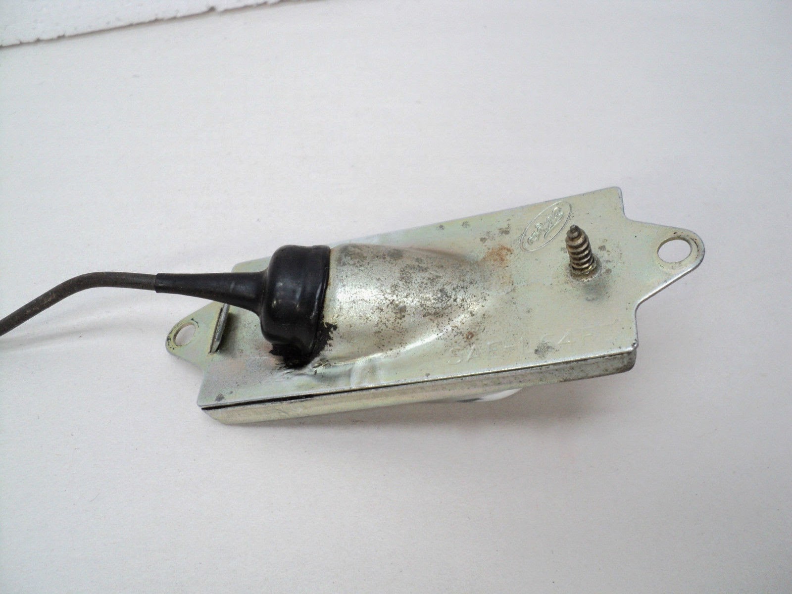
The optional gauges slip through the front of the bezel and held in place by the gauge housing by 2 nuts secured to the same posts that the wires connect to. Make sure the gauges are straight before gently tightening the nuts with a 3/8" wrench, taking care not to over tighten and cracking the bezel.

Mount the gauge on the bezel by pushing gauge through front
Mounting the New Gauge Rings on the Old Lens:
Newly painted rings on old lens
Mounting the inner gauge rings took a little finessing as the bottom mounting tab on the back of the ring is manufactured 1/16" of an inch lower than the originals. The two top tabs fit in the original holes perfectly, so I took a pair of wire cutters and snipped off the bottom tab on each of the two rings. Slipping the two top tabs into the lens, I dropped a little gorilla glue into the tab holes and let dry, securing the rings to the face of the lens.

Mount Old Gauge Cluster in the New Bezel:
Turn the bezel on its face and slip the lens in place, then mount the primary gauge cluster aligning the little tabs to ensure a tight fit. The cluster only fits one way the seven retaining screws hold firmly.
Reassembled Bezel


Mount the complete Instrument Cluster in the Dash:
Now comes the fun part, positioning the new bezel into the dash I re-connected the wiring from left to right checking against pictures I took before removing to unsure correct wiring; saving the speedometer cable until last and attaching this by reaching up behind the dash and turning the single nut until hand tight,.
!966 Instrument Cluster
Quite a difference !!!
Old v. New 

Sunday, October 12, 2014

Refreshing the Optional Gauges

Old Blue came from the factory with the optional Alternator and Oil Pressure gauges mounted on the outer flats of the bezel. To mount them I will have to drill holes for each of them in the reproduced bezel, however before doing this, I will clean the chrome, polish the plastic and repaint the needles so they are fluorescent red again instead of the faded orange they are today.
1966 Ford F-250 Custom Cab Instrument Cluster

Tasks:
1. Breaking down each gauge
2. Removing rust and polishing chrome on the rings
3. Polishing the plastic lens
4. Painting the needles

ALT Gauge removed from bezel - rust on face ring 
Breaking Down the Gauges
To clean the gauges I will break them down to their components parts, which requires a small flat head screwdriver to pry up the retaining tabs located around the lip of the chrome ring. There are 5 tabs and you want to take care not to bend them back and forth as they can break off with too much movement.

Removing Cover Ring

Lift the tabs and the chrome ring separates from the gauge housing, allowing the plastic lens holding ring to be lifted off the gauge. The lens separates by gently pushing up from the back of the holding ring.


The lens holding ring has a slot at the top and the lens fits into this slot to allow light from the bulb in the gauge housing to illuminate the face of the gauge at night. The lens can only fit one way into the holding ring.

The lens is plastic

The Face plate on these gauges are chromed metal and the inner face is painted argent just like other surfaces on the bezel.
Removing Rust and Polishing the Ring: 
Face Ring 
The ring has rust and pitting on the chrome so we will use the same techniques we use with our bicycle handles ... using aluminium foil dipped in a little water, we rub the surface of the chrome lightly removing rust and bumps. I want to take care not to mess with the argent inner surface as I do not want to repaint since they are in pretty good shape.

I will use Mothers Chrome polish to shine up the surface and we should be good to go !

Polishing the Plastic:
The plastic lens has a few scratches and is dirty so we will use the Novus product recommended by TAP plastics to remove scatches in plastic and to give the surface a clean surface. The Novus products work well and I use the #2 and #1 only on the gauge lens. I carefully avoid the white paint on the lens (OIL / ALT) so I do not mess up the original mask.
Plastic Scratch Remover and Polish 
Painting the Needles:
The needle in the gauge has faded through the years and is now a light orange color. Reading on the FE forums from others who have refreshed their gauges I follow their recommendations and get a RED FLUORESCENT paint pen from the local Michaels. I selected the liquitex brand. Everything I read said to make sure you get fluorescent paint as normal red will not show up as well when driving at night with lights. 

I slip a piece of newspaper between the
Ready to paint needle
needle and the black background to keep from messing up the black and gently apply the red paint to the needle ... 
Red Paint Pen

The needles are delicate and move around a bit. I took care not to push too hard or to bend the needles and just gently stroked on the paint, occasionally, pushing the pen down on a piece of newspapers to keep the paint flowing. The shape of the needles required I paint the left side and right side separately, doing a couple of coats to cover the needle completely.

Reassembling the gauge is just the reverse of the tear down process, once again take care when bending the ring tabs.
Refreshed Optional Gauges
I am pretty happy with how they turned out. 


Saturday, October 11, 2014

Taking Apart the Instrument Cluster

The 1966 Custom Cab instrument cluster is comprised of 4 standard and 2 optional parts that tear down and re-assemble fairly easily. The parts include :
  1. Front Bezel - Chrome finished plastic that all pieces attach to and then it is screwed to dash
  2. Primary Gauge Panel  - includes the speedometer, Fuel and Temperature gauges
  3. Lens - has the white lettering for each of the gauges
  4. Two front gauge rings - one each for the Fuel and the Temperature gauge
  5. Two optional gauges (ALT/OIL Pressure)
Removing the primary gauge panel is very straight forward. Laying the cluster face down on a soft suface, remove the 7 screws from the back of the panel with a phillips head screwdriver.
Location of gauge panel screws
Gently lift up the panel revealing the plastic lens and lay the panel aside. The Lens is just laying in the bezel so lift up using the edges to keep from leaving finger prints on the lens. This leaves the two optional gauges in the bezel. To remove them, first take off the wire retaining nuts and split washers if you haven't already. The gauges are held in place by two additional nuts on the same gauge posts as the wiring but tightened to hold the housing against the bezel.
Optional Gauge Mounted on Bezel
With a 3/8" wrench remove the housing retaining nuts which release the gauge through the front of the bezel and the gauge housing on the rear. Both the gauge and housing should drop away but may need a little wiggling or pressure after sitting in place for 50 years. The gauge itself comes out the front of the bezel while the gauge housing comes off the back.  Repeat for the other optional gauge and this should leave the bezel as a single piece of plastic.

Argent Shadows For The Bezel

The new parts that I will use for the replacement instrument bezel will need to be painted to duplicate the details of the original bezel. In 1966, Ford applied argent paint to any inner surface of the instrument cluster to reduce the glare from the dashboard lights at nights. The reproduced versions (as well as the re-chromed versions) do not have this detail element so we will add the argent to both the bezel and the gauge rings.


Original bezel showing argent colored surfaces

The reproduced bezel from Dennis Carpenter comes with all surfaces chromed. People on the FE forum also report when they have their original bezels re-chromed they come back with all surfaces chrome.

Reproduced bezel showing chrome colored surfaces
So, first I will need to remove the gauge rings from the lens and then mask off the parts I want to keep chrome with blue tape.

The gauge rings are attached to the lens by 3 round posts that are inserted into 3 holes in the lens with the ends of the posts then melted to hold in place. To remove I used my fingernails to break off the melted part of the post and then gently pulled the ring from the face of the lens. I did this same procedure for both rings.
New Lens with Gauge Rings

I will paint both of the inner gauge rings and then do the same for the bezel. After wrapping with blue tape, I used an exacto knife to cut the tape to cover only the areas I want to stay chrome and  cover the remainder of the bezel with newspaper to protect the chrome finish. 


I used my usual VHT SP-188 for the Ford argent, this color is not to glossy but is not totally flat like primer.


I carefully applied two light coats of the Ford argent to the bezel inner face, letting each coat dry before adding the next. I did not sand or buff in any way as the paint was looking smooth over the chrome and I did not want to mess up an acceptable accent to the new bezel.

While the paint is drying I will take a look at the optional gauges and see what can be done to freshen them up a bit.

Friday, October 10, 2014

The Reproduced Bezel Arrives

The reproduced bezel took a week to come and upon inspection I noticed a few differences from the original.
  1. The flat argent on the inside of the viewports was as expected ... not there. It was painted the same shiny chrome finish as the rest of the Bezel.
  2. The lettering on the lens was in a different font than the original. Is flat and fat compared to original equipment manufactured by FoCo. 
  3. The holding tabs for the chromed frames for the FUEL and TEMP were not in the same position as the originals.There are 3 tabs holding each of the rings on the lens. The bottom tab of the reproduced set is placed 1/16" lower on the ring. 
  4. The M in the lettering for 'TEMP' was smudged and messed up ..Overall manufacturing quality of the bezel as well as the lens was less than the OEM.
    Mask Quality of Reproduced Lens
Other than these items the chrome finish was bright and beautiful and a much better finish than I got with the chrome colored rattle can stuff. So, I think the plan for refreshing Old Blues Instrument Cluster will be a mix of the new parts and the old parts to retain as much of the vintage elements as possible. Tasks include:

  1. Clean old plastic lens and use with new bezel
  2. Clean both optional gauges (Alt and Oil Pressure) - Chrome polish outer rings, buff plastic lens, paint needle
  3. Use the new chrome rings mounted on the old lens for standard gauges (Fuel & Temp), paint the inner face of rings Ford argent
  4. Paint the new bezel's inner face Ford argent 
  5. Paint needles of speedometer and standard gauges fluorescent red.


Tuesday, October 7, 2014

Painting the Original Cluster with Krylon Chrome


While I was waiting for the repro bezel to ship, I went ahead and painted the old bezel with some rattle can chrome. I had removed the gauges, lens and optional parts and decided to retain the argent as it was in pretty good shape.

Masking the Ford Argent
Masking off the argent lips was easy and I decided to try Krylon Chrome as it looked to be the shiniest paint on the shelf.
Masking the bezel and rings.

I started by painting the outer face of the two rings from the lens, masking off the inner argent to retain the semi-gloss gray.


The rings painted up fine though the color was more gloss silver than chrome. 

Now on to the bezel ... I messed up by putting on 2 coats of the Chrome paint. Though very light coats, the paint was thick and the left side was not as crisp as I would have hoped. However the color was much more chrome than the rings and not bad for a paint job. I could still see the tooling patterns on the face and I put the gauges back on to check out the results. 
Painted Bezel
 It turned out OK but was a far cry from what I was hoping to accomplish. Overall the bezel seemed more silver than chrome, though I was able to retain the soft argent non reflective inner panels. 


Sunday, September 28, 2014

What to do about the Instrument Cluster?

Old Blue has the original instrument cluster with the appropriate custom cab sweep speedometer on her dash and these days the silver coating is mostly gone from the face of the cluster bezel, replaced by a yellowish plastic finish that needs a refresh.

The part in question has been identified by Bill on the FE forums as
 " C5TZ10838A .. Instrument Cluster Bezel-Plastic / Original applications: 1965/66 F100/250 2WD Custom Cabs. and they are not made by Ford any longer so replacing with another OEM part is not an option.". He continues "Carpenter has reproduced it, but...It does not come with holes for the optional Oil & Amp gauges. Neither did the original bezel, and just like the original, a hole saw has to be used to cut the holes. Ford only supplied the bezel with Oil/Amp gauges on factory assembled trucks, it could not be purchased at the parts counter."
__________________
Bill / Retired Ford Parts Manager / Part number research: 1928/2001 trucks & 1928/89 passenger cars.

Thanks Bill!

Options
Reading through the comments from the smart boys at the FE forums we have four options for bringing the cluster back to life:
1. Remove and replace with a reproduced one from Dennis Carpenter's for about $150+shipping. Described as "CHROME PLATED PLASTIC BEZEL CLEAR LENS WITH WHITE LETTERS & CHROME PLATED PLASTIC RINGS FOR THE FUEL & TEMP GUAGES". Notice the flat argent (dull silver) paint is missing from the inner side of the rings and border per original.

2. Remove and replace with one saved from another 1965/66 Custom Cab Ford truck I looked around eBay and craigslist for some current offerings and found the following with a starting price of $129 and 18 watchers waiting to snipe !! It is scratched and in need of refinishing, however, it DOES show the flat argent on the inner surfaces of the rings and bezel.

3. Remove and send the plastic off to a shop to have a chrome finish applied

Dave on the FE forums has a 65 F100,and showed us this cluster he had refinnished. Notice the flat argent (dull silver) paint is missing from the inner side of the rings and border per original,.however, surface is bright and tooling crisp!

4. Remove original and paint with modern chrome paint.


Considerations:
1. The reproduced clusters do not have the (as original) flat argent paint applied. Used on the underside of the surrounding lip to prevent glare at night.They cost about $150 plus shipping at Dennis Carpenters. Would have to apply the flat argent after purchase.
2. Costs are over $100 for refinishing the old, and would still have to apply the flat argent paint to inner surfaces to reduce glare per original.
3. Finding a used OEM that is in better shape than the current bezel on Old Blue would not give me much benefit as I would probably have to refinnish or paint anything I find on Ebay.
4. I am a horrible painter :)
5. Any replacement would need holes drilled for the Alternator and Oil Pressure gauges.
6. I could just leave things as they are and claim 'Its the patina of a 50 year old truck !'

Decision: 
I decided to get a reproduced bezel from DC and will paint the inner lips Ford Argent to match the original bezel. I ordered a reproduction from Dennis Carpenters.

I should also mention  that Old Blue has the additional and custom factory/dealer installed Alternator and Oil Pressure gauges mounted on the bezel and so before doing anything we will need to disconnect the battery. The Alternator gauge is wired inline to everything so we do not want to accidentally short circuit anything.

Original Instrument Cluster from Old Blue

How to remove the cluster from the dash:  
  1. Take the negative cable off the battery
  2. Unscrew the speedometer cable from the back of the cluster by reaching up behind the dash, it is big and fat and the single screw came off with my fingers. 
  3. Remove the four bottom and four top screws from the face of the bezel with a phillips head screw driver. 
  4. Pull the top of cluster forward a couple of inches to expose the wires in the back 
  5. Start from right and work your way left, taking pictures and labeling wires as needed. My wires had been in place for so long, that even though I took pictures of every one, they stayed right where they had been for the last 50 years  [NOTE : Take care with the light bulbs and the three flat slide-on connectors in the middle of the back of the bezel. The light bulbs can  be stubborn to pull out and you want to be sure to label each as they all look similar and it will slow down re-installation if you get them mixed up. The 3 flat slide-on connectors only go on one way as all three are different but be sure to take pictures to get them right. Also, the connectors to the custom factory gauges are different than the Fuel and the Temp which have simple round slide on (2 each gauge) and a bulb. For the custom gauges, you will need to remove 2 nuts and a lock washer for each gauge using a 3/8" wrench. Old BLues were very tight but not not require WD-40.] 
  6. After working your way to the Alternator (or furthest left gauge), there are two metal braces holding the wrapped harness of the cluster wires on the bottom of the back of the bezel. These are U shaped holders and you should be able to just lift the harness out of the holders to release the bezel. 
Bezel Background: 
This is: C5TZ10838A .. Instrument Cluster Bezel-Plastic / Original applications: 1965/66 F100/250 2WD Custom Cabs.

Carpenter has reproduced it, but...It does not come with holes for the optional Oil & Amp gauges. Neither did the original bezel, and just like the original, a hole saw has to be used to cut the holes.

Ford only supplied the bezel with Oil/Amp guages on factory assembled trucks, it could not be purchased at the parts counter.

The bezels come with the optional gauges, no one repro's them. NOS or used are the only alternatives. When these gauges are present, there is a separate wiring harness for them that plugs into the dash harness. How are the aftermarket gauges wired? 

The Custom Cab plastic chrome sweep speedo instrument cluster bezel (1965 F100/250 2WD, 1966 F100 4WD) is repro'd, but it does not come with holes for the oil/amp gauges which were an extra cost option.

When the oil gauge is present, there's a fitting that threads into the block that both the oil warning lamp switch and the oil pressure switch thread into.


C5TZ-9273-A .. Oil Pressure Gauge / Obsolete 

C5TZ-10850-A .. Ammeter Gauge / Obsolete 
__________
Bill / Retired Ford Parts Manager / Part number research: 1928/2001 trucks & 1928/89 passenger cars.

Monday, July 14, 2014

First Anniversary

It has been 1 year since Old Blue rolled off that Auto Transport out in front of Casa and the kids and I are feeling pretty good about the level of stewardship we have committed to the 1966 Ford F-250 Camper Special.


All the 'Cool Truck' comments
Without fail, when we drive Old Blue we get comments and horn beeps from admirers of the blue and white '66 Slick. Many people stop to talk about similar trucks they owned in the past, or that their parents or some other relative had owned something similar. Sometimes they talk about their memories of driving around in an old truck and share something special to them. The kids and I never know what to expect when we pull into a gas station, a grocery store, or even just stop at a red light. People respond to the classic lines and paint scheme in a way that harkens to days past, when communications were simple and it was OK to show true emotions to strangers.

The truck touches something in young and old people alike. We are often asked about what year it is; and have taken to responding with 'Take a guess' ! It is amusing to hear younger kids think this old steel monster came from the 80's or 90's !!! When they hear it is from 1966 they are surprised and amazed it looks 'so new' for a 50 year old truck.

We have settled many a bet between people - couples guessing what year it is while driving down the road, when they pull up beside us at a light or stop sign and calls out "Is that a '65?" When we answer there are smiles and whoops and more stories about  how one or the other made their guess.

Lessons Learned 
Driving Old Blue around town opens doors to many areas of interest for us. I listen to the kids talking when we are cruising and I think they get a sense of how she reflects the golden age of american manufacturing, her place in the evolution of automotive engineering, and even problem solving strategies - all unexpected benefits of taking on the stewardship of the vehicle.

My youngest son immediately recognized the difference in analog technology versus digital and comments frequently how Old Blue runs and displays information just like his mothers Honda but without any computers. This often leads to discussions on how automotive engineers from the past could create sensors and circuits to communicate data to the drivers of these old autos with NO digital processing available to them. Our trips to school in the morning, when not focusing on vocabulary words or math functions typically include some discussion about 'Fuel/Fire/Air' translating into simple physics perspectives of torque, power, motion - we stay away from talking about collisions except to note that 2 tons of heavy american metal is no match for the plastic in cars built today!


Saturday, April 19, 2014

The License Plate Light

While painting the back bumper I had noticed that the license plate light was not working. I did not know if it was the bulb, the housing or the wiring but today I decided it was time to find out and keep Old Blue legal for night time cruising.

I started by taking a close look at the housing as in order to get to the bulb I would have to disassemble it. There was a single small screw to lift up the top of the frame and the heavily painted bulb cover. I could not get the screw loose as it was rusted and when I looked to take the complete housing off the bumper to make disassembly a little easier I saw that the two small bolts and nuts were also heavily rusted. I shot all 3 with WD-40 and let sit over night.
The light behind protective bar
The next day the nuts, bolts and screw were just as tight. I took a closer look at the setup and decided to find out more about the light housing and the bulb. The housing had been painted over 3 or four times in silver paint and then had rusted over the last 50 years so it was a mess - maybe it made more sense to just cut the whole thing off the bumper and buy a new one?

A quick search through the FORD F-250 Manuals showed me the part number was "C3AZ-13550-1157"  and that this part was identified as a alternate for the round button shaped license plate lights used on trucks sold with rear bumpers and identified as the correct light for 'bumperless' trucks.
Original Lamp Housing

We know Old Blue has an aftermarket bumper as FORD did not offer a step bumper in 1966, so the part looked correct. Searching on EBAY I found a used one for $29.99 + $19.55 shipping (WOW!) that would be $50.00 for a replacement!
From http://www.fordification.com/.


I decided to search on the part number number and found that 65 Mustangs, Rancheros, Falcons all  had used the same housing but with a substantially shorter cable. I found one on EBAY for about $18 with shipping. I guess I could use this for Old Blue with a few modifications but decided I would try to salvage the rusted, painted one currently on the old truck.

Rollling under the back bumper I put a socket wrench on the old nuts holding the light housing to the back bumper and gave it a good twist .... the bolt snapped in half just behind the nut ,,,hmmm .. that worked out O.K. will the other do the same? I tried the second bolt and yep, it also snapped in half right behind the nut. I grabbed a punch and a hammer and gave the remainder of the bolt a soft whack and it pushed through the bumper and the housing and dropped the ground near my legs, the same for the other bolt and after 50 years the light housing was loose from the bumper. I firmly grabbed the housing and using the largest screw driver I had I carefully unscrewed the single screw holding the glass bracket to the housing. As the screw backed out the glass bulb cover fell into my hands along with the remainder of the bulb. The bulb  was almost nonexisitent having fallen to bits over the years. I laid the glass shade aside and dropped the glass bracket into a jar of Phosphoric Acid for an overnight soak. I took a closer look at the bulb and noticed it was labeled with 83, so later that night I took a ride over to the local Autozone, O'reilly's and Napa stores. None of these stores had type 83 bulbs so I wondered if this was the right bulb for the 12v system on Old Blue or had this been a just in time replacement ?

While sitting in the parking lot of the Napa store I googled for the part number 13550 and found a conversion table at the fordification.com website. Here I found the recommendation to use Industry number bulb 97 which replaced the FORD part no. C3AZ-13466-G. I went inside and bought 2 type 97's for about $5.

Having pulled the glass holding bracket and glass bulb cover I took a closer look at the light fixture. It had a single cable coming from somewhere behind the bumper that ran through a waterproof plastic holder, through the metal mounting clip through another plastic washer terminating with a brass cover. The parts were all rusted and covered in dirt.
Back plate with power feed


Back plate with bulb removed
The back plate had a rubber gasket to keep the water out which I removed because it had deteriorated over the years.I cut out a new one from some old rubber inner tube I had laying around and replaced the bulb with a Type 97.
New Gasket 
I buffed the glass lamp cover and the outer frame and found a couple of bolts, locking washers and nuts to remount the assembly.
Ready for Re-Assembly
Remounting was straight forward and when It was complete I fired up Old Blue, turned on the lights and ran back to take a look at my handy work - OH NO .. the light did not work.

After shutting down the engine and turning off the lights I rolled under the back bumper and followed the wire from the light assembly back to the connector plug into the wiring harness just as the wiring diagram had indicated. The cable had been extended so the bumper could be moved out under the old camper that Uncle Ken used to have. The wiring looked fine with no breaks so I pulled the harness connector plug and sanded the connector shiny, and reinserted it.

I fired up the engine again, turned on the lights and ran back to take a look.and PRESTO! the light was shining bright! Job Done.
Working License Plate Lamp


[This document shows how to remove the rear license plate housing and replace the bulb on a Ford F250 Truck]

Sunday, April 6, 2014

Finding Out Why the Wiper Switch Does Not Work

Old Blue's windshield wipers stopped working in December while we were driving out to Point Reyes for a soccer game. The rain was light so it really didn't matter much and we do not plan to drive her in the rain but I was curious why they just stopped responding to the turn of the switch.

1966 F250 Camper Special Wiper Switch

Checking around the web I find some additional info regarding the '66 Ford Truck setup. Some '66's have the windshield washer switch integral with the wiper switch. Some (if equipped) have a separate push button washer switch above the ignition switch. Some have a foot activated floor mounted pump.

In 1966 both single & two speed wipers were available. If you can only turn the wiper switch one 'click' you have the Single Speed switch. If you can turn the switch twice it is a two speed switch. Old Blue has a 2-speed switch and pulls out which should control the washer function. However, Old Blue ALSO has the push button above the ignition key and it is wired to the the washer motor through the firewall but not grounded. I will have to check this out someday.

Removal:
It took a while to figure out how to remove the switch from the dash. Once you get it the procedure is quite simple, as follows:
1. Remove Knob : This is done by pushing a small screwdriver into the slot at the base of the knob, releasing the metal catch inside from the groove on the switch post and pulling knob gently off post. It took me a few times to feel the metal catch inside the knob with the screwdriver and to figure out how much pressure to apply (not much is needed) and when the latch slips the knob easily pulls off the post.

Slot to release catch
'D' shaped pressure catch inside knob
This same knob is used for other controls on the dashboard; I practiced with the heater control because it was easier to get to until I figured out where and how much pressure was required to release knob from the post.

2. Remove Bezel nut: I decided to remove the switch from the dash and then get underneath the dash to remove the wiring. the switch is seated in the dash by a simple slotted screw. I took a large flat screw driver and gently pushed counter clockwise on the slots - the screw spun right off.

Wiper switch bezel and retaining nut

The silver bezel marked 'Wiper' just lifted off the post and underneath the Wimbledon White paint was unfaded or marred. I could just imagine what Old Blue's dash looked like when she came off the assembly line.

I reached my hand up under the dash and gently pulled the switch and connected wires down a little so I could take a look at how they were attached.
You can see the 'gap' between the female connector and the switch housing

There are 5 wires connected to the switch and after looking carefully I notice the black parts are a male-female connector.

I gently encouraged (with my flat head screwdriver) the male connector out, turning the switch to expose three different leverage points and applying minimal pressure to each to move the parts (I was worried I might break the old, brittle plastic bits) until the switch fell lightly into my hand.

Turning it over I noticed how grungy and dirty it was and that the female wiring connector was loose from the switch housing. Leaving a gap along one side about 1/8" wide which I could close by pressing the wiring connector against the housing. It sprung back when I released the pressure. Hmmmmmmmm

Holding the switch in my hand, I could turn the post from left to right and back, feeling the two clicks but I noticed that when I pushed the connector against the housing the clicks were solid and when I let the pressure off the connector allowing it to 'gap' and then turned the post the clicks were almost non-existent.

Cleaning:
I shot the switch through the 'gap' between the housing and the connector with electrical contact cleaning fluid, worked the switch back and forth a few times and then repeated multiple times. I let it dry and then with a damp cloth wiped all the gook and dirt off the exterior of the switch. Moving the post again, the switch was moved much more freely now ...

While I had the knob off the post I thought I would figure out how to clean it. These knobs on Old Blue are ALL caked with a white substance that fills the grooves in the knob (see in pics above) and I have tried various cleaning products and brushes to get this stuff off the knobs but nothing seems to work very well.
Electrical Contact Cleaning Fluid 
The cleaned switch

I dipped the knob in water and took a toothbrush and brushed the grooves - after drying, the white stuff was still there. I took a wooden toothpick and ran it along the inside of the grooves - this removed the white gunk so I laboriously did this multiple times in EACH groove removing the white gunk and leaving the knob black and shiny. Sometimes elbow grease is the only answer ...

Mind The Gap:
I looked closely at how the connector was attached to the housing and saw 4 metal tabs on the housing that were pressed against the plastic edges of the connector. On the side with the 'gap' the 2 posts were loose from the plastic, allowing the connector to retreat from the housing. Taking a pair of wide mouth pliers I positioned the teeth of the pliers to just set on the metal posts, pressed the connector solidly against the housing and applied pressure - lots of pressure - to bend the little posts against the plastic. After a few times of doing this with both posts the connector stayed solidly seated  against the housing.
Re-seating the retention tabs to 'Close the gap' 
Re-Installation:
Putting the switch back into the dash was straight forward now that I knew how the various pieces fit together. I connected the wiring harness to the switch, fed it back through the hole in the dash, put the bezul on (there is a little nub on the back to help with alignment of the bezel) and screwed the retaining nut back into place using my screwdriver for the last bit to ensure it was tight. The knob slipped right back on and clicked into place.

I fired up old blue not knowing if I had fixed anything and moved the wiper knob to the right 1-click. The windshield wipers started moving back and forth - EUREKA !!!

I moved the switch to the second position and watched as the wipers picked up a little speed and then turned the switch back to the left and watched as the wipers gently glided to their resting place on the windshield. I repeated just for fun with the same results and felt lucky the problem was probably that the 'gap' allowed space to come between the metal sliding connectors inside the switch keeping them from completing the circuit OR maybe some gunk in the switch that had been blown out when I shot it with contact cleaner.

Information:
Once again Bill from the Ford Enthusiasts website has something to say about these switches:

C6TZ-17A553-B .. Two Speed Wiper and Windshield Washer Switch-terminals, includes w/shield washer switch / Marked: C6TB-17A553-B (Motorcraft SW-736)/ Obsolete

Applications: 1966 F100/350 from serial number 760,001 / 1966 F500/950 from serial number 802,001.

The serial number is the last 6 digits of the VIN, use this to verify the switch you need.

[This document shows how to remove the wiper switch from a Ford F250 Truck]